


Effects of harmonics caused by VFD of the HVAC loads in the modern power systems
06/05/2020
A.Harmonics and its source
Harmonics are a power quality problem. Harmonics are distortion on a power system and give a bad effect on components and equipment of electrical systems which originally designed to operate at ideal sinusoidal current.
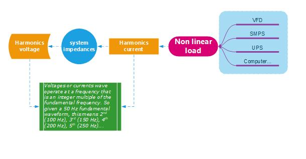
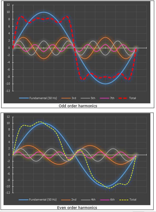
- Harmonics are sinusoidal component wave (voltages or currents) operate at a frequency that is an integer multiple of the fundamental frequency. So, given a 50 Hz fundamental waveform, this means a 2nd harmonic frequency would be 100 Hz, a 3rd at 150 Hz, a 5th at 250 Hz…
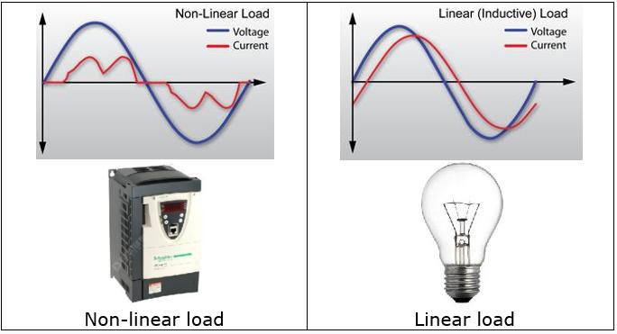
- Harmonic currents are caused by non-linear loads connected to the distribution system. A load is said to be non-linear when the current it draws does not have the same waveform as the supply voltage. The flow of harmonic currents through system impedances, in turn, creates voltage harmonics, which distort the supply voltage.
- Examples of nonlinear loads such as are switch-mode power supplies (SMPS), variable speed motors and drives, photocopiers, personal computers, laser printers, fax machines, battery chargers and UPS. Single-phase & three-phase non-linear loads are prevalent in modern office buildings and factories and industrial plants.
Odd order harmonics distort the sinusoidal current to a form of pulse, which creates a great risk of overload for inductors (reducing the total resistance of the inductor) in electrical devices which designed to operate in AC voltage.
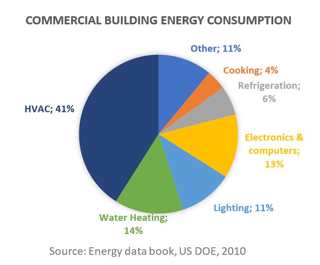
B.Why HVAC load contribute the biggest harmonics back to the power grid?
Currently VFD is used in many devices in the HVAC system, moreover, the HVAC system also accounts for a large proportion in power consumption of a building (about 29 ~ 43%) so VFD is typically the largest contributor of harmonics back on to the grid.
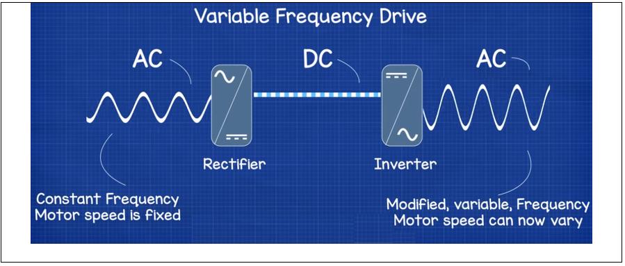
C.How VFD create harmonics?
The harmonics occur because the current cannot flow through the rectifier and enters the inverter when the input AC voltage is less than the DC voltage on the capacitor. This only happens for a short period of time on each phase but is enough to completely deform the input AC current so that it is no longer a standard sinusoid. Moreover, due to being blocked by the difference between AC and DC voltages at the input, the current must have a higher peak amplitude to transmit enough power to the motor in a grid cycle.
D. The trouble with harmonics in modern power systems
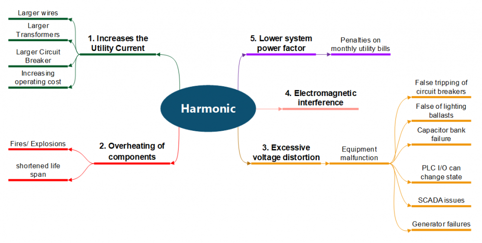
- Increases the utility current: Resulting in need for larger capacity of wires, transformers, circuit breaker and increasing operation cost
- Overheating of components: causing fire/ explosion and shortened life span of electrical distribution equipment, cables, transformers, generators, etc.
- Excessive voltage distortion: causing equipment malfunction such as
- Electromagnetic interference: Harmonics caused strong electromagnetic interference, thus create noise in equipment (DB, MSB...), flashing screen, noise in PA system…
- Lower system power factor: resulting in penalties on monthly utility bills False tripping of circuit breakers Loss of lighting ballasts Capacitor bank failure PLC I/O can change state SCADA issues Generator failures…
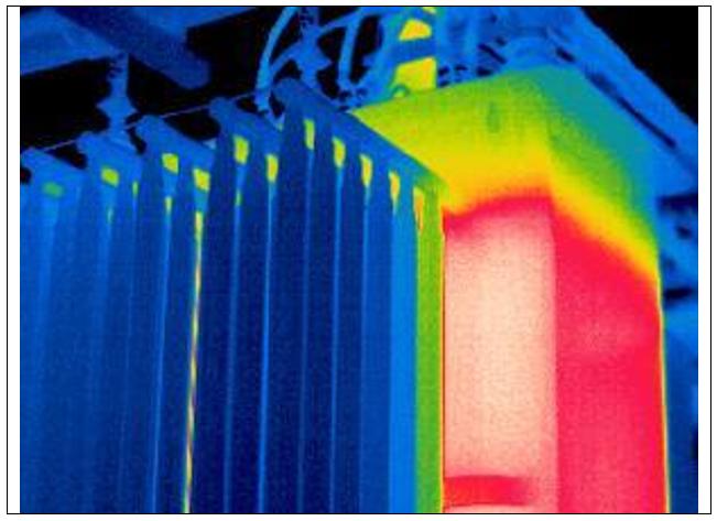
E. Some examples of harmonics effect
Overheating Distribution TransformersEddy currents due to stray flux losses cause excessive overheating. Increased heat by 7-10 degrees can reduce 1/2 the life of insulation
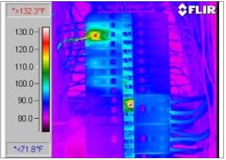
Tripping of Breakers
Harmonic current peak values can be many times higher than sinusoidal waveforms, that cause false circuit breaker tripping.
Cable Insulation Breakdown
Harmonic currents with Higher frequencies cause electrons to flow toward the outer sides of a conductor, this reduces the ability of the conductor to carry current, so reduces the ampere capacity rating of the conductor and adds more heat could cause cable insulation breakdown.
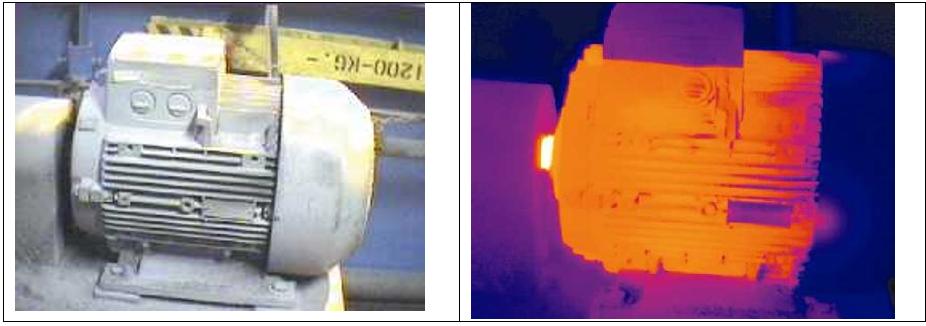
Motor thermal problems
Higher frequency voltage components produce additional hysteresis and eddy current losses in the core of AC motors. These losses increase the operating temperature of the core and the winding surrounding the core and may cause undesirable torque pulsations.
Harmonic currents with Higher frequencies cause electrons to flow toward the outer sides of a conductor, this reduces the ability of the conductor to carry current, so reduces the ampere capacity rating of the conductor and adds more heat could cause cable insulation breakdown.
Motor thermal problems
Higher frequency voltage components produce additional hysteresis and eddy current losses in the core of AC motors. These losses increase the operating temperature of the core and the winding surrounding the core and may cause undesirable torque pulsations.
Generator Problems
Excessive harmonic distortion will cause multiple zero crossings of the current waveform, affecting the timing of the voltage regulator. This can cause the generator to shut down.
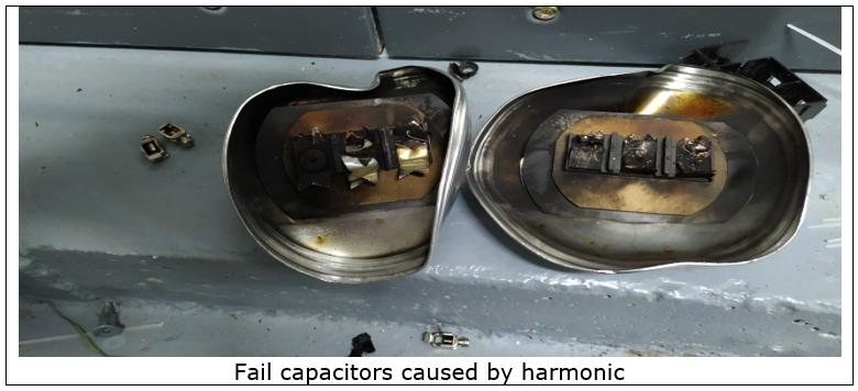
Power Factor Capacitor Problems
Harmonic distortion has a direct effect on power factor. More harmonics = lower power factor. The heat losses generated by harmonics transpose into using and paying for reactive power and harmonic current can cause capacitors to fail.
Excessive harmonic distortion will cause multiple zero crossings of the current waveform, affecting the timing of the voltage regulator. This can cause the generator to shut down.
Power Factor Capacitor Problems
Harmonic distortion has a direct effect on power factor. More harmonics = lower power factor. The heat losses generated by harmonics transpose into using and paying for reactive power and harmonic current can cause capacitors to fail.
F.Harmonics limit
Due to the dangers of harmonics on power system, thus the management of harmonics in the electrical system is considered a common responsibility related to both the electricity supplier and customers to ensure the quality of electricity in accordance with the requirements of regulations. Below are some regulations and standard of harmonics limit.
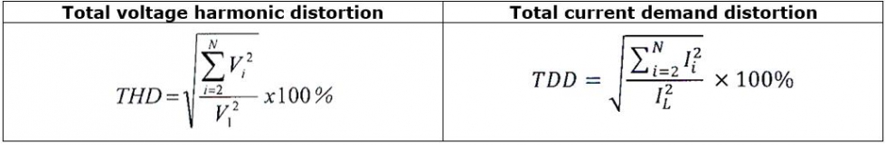
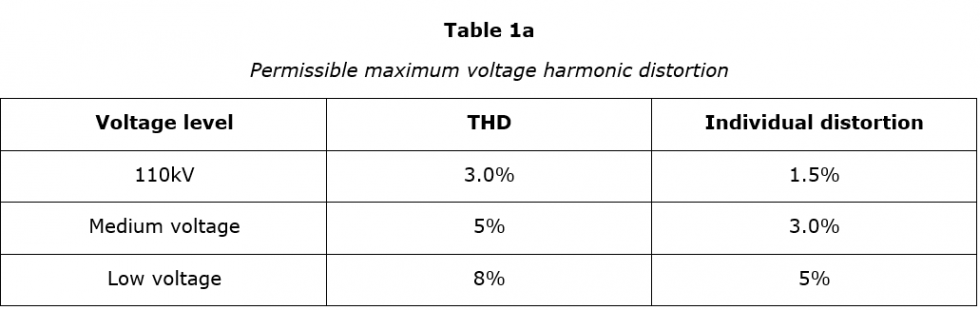
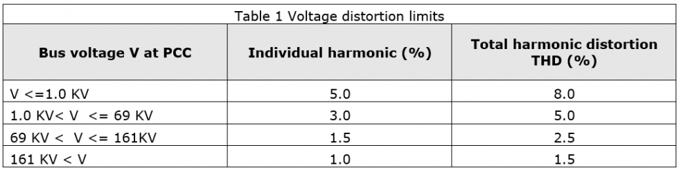
- Voltage distortion limits
- According to Circular No. 30/2019/TT-BCT
- According to IEEE 519 standard
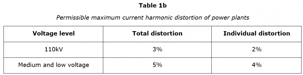
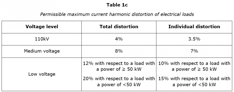
b. Current distortion limits
- According to Circular No. 30/2019/TT-BCT
- According to IEEE 519 standard
- Current distortion limits for systems rated 120 V through 69 kV: See Table 2
- Current distortion limits for systems rated above 69 kV through 161 kV: See Table 3
- Current distortion limits for systems rated > 161 kV: See Table 4
G. Harmonics mitigation method
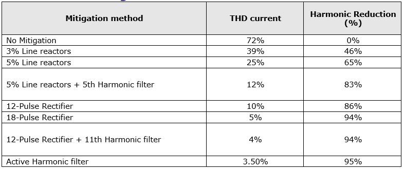
With the increasing demand for non-linear type of equipment and loads, mitigation of harmonic becomes more and more important. Depending on the situation, there are typically several mitigation methods to choose from:
- Limit the amount of non-linear loading
- Isolation transformers
- Line reactors
- Using 12-pulse or 18-pulse instead of 6 pulse drivers
- Harmonic trap filters
- Passive filters
- Active filters
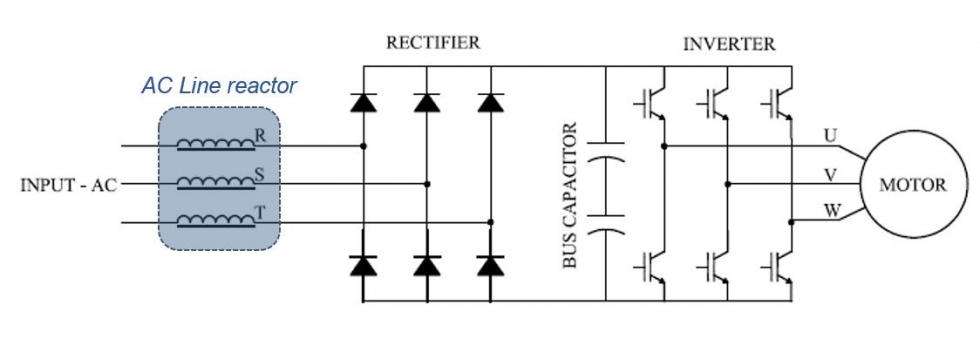
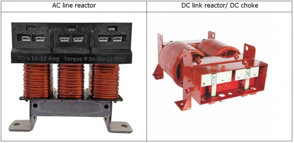
- Line reactors
- AC line reactor: When a reactor is installed between the power system and the VFD
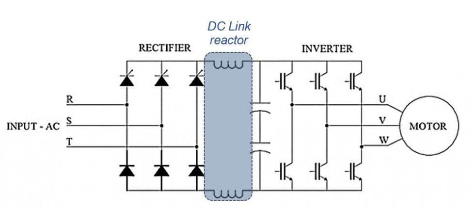
- DC link reactor/ DC choke: When a DC reactor is inserted into the DC link of a drive.
b. 12-pulse and 18-pulse drivers
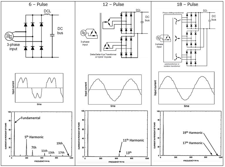
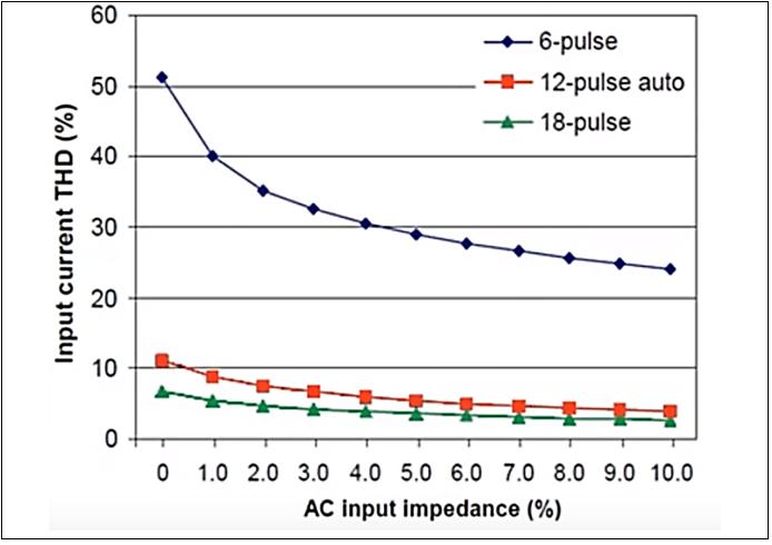
The graph below shows harmonics curve and harmonics current in percent of fundamental current which would yield by a 6-pulse, 12-pulse, 18-pulse rectifier. The graph also indicates that the 12-pulse and 18-pulse rectifiers would yield less harmonic current then 6-pulse rectifier
The graph below shows harmonics curve and harmonics current in percent of fundamental current which would yield by a 6-pulse, 12-pulse, 18-pulse rectifier. The graph also indicates that the 12-pulse and 18-pulse rectifiers would yield less harmonic current then 6-pulse rectifier
- A 6-pulse rectifier would yield harmonic current at the 5th, 7th, 11rd, 13th, 17th, 19th etc. harmonics
- A 12-pulse rectifier would yield harmonic current at the 11th, 13th, 23rd, etc. harmonics
- A 18-pulse rectifier would yield harmonic current at 17th, 19th, 35rd, 37th etc. harmonics
The graph below shows the effect of increasing the AC input % impedance on the input current
- The choke is characterized by its ability to block high-frequency currents (ZL = ωL = 2πfL, the bigger f is, the bigger the ZL) so increasing the input impedance corresponding to the addition of the reactor will be very effective in filter high harmonic current
- The 6-pulse rectifier cannot reduce the input current THD below 25% even with an input AC reactor with 10% impedance
- The 12-pulse and 18-pulse rectifiers can achieve an input THD of less than 10% with the addition of input AC reactor of 1-2% impedance
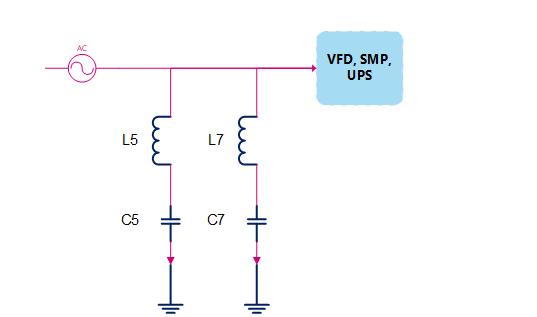
c.Passive Harmonic Filter
Passive Harmonic Filters provides a low impedance path for the major harmonic currents. This greatly reduces the amount of harmonic current flowing through the distribution system and results in improved power factor, lower RMS currents, lower harmonic current distortion, lower harmonic voltage distortion, and increased system capacity.
Passive Harmonic Filters provides a low impedance path for the major harmonic currents. This greatly reduces the amount of harmonic current flowing through the distribution system and results in improved power factor, lower RMS currents, lower harmonic current distortion, lower harmonic voltage distortion, and increased system capacity.
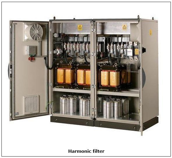
d.Active Harmonic Filter
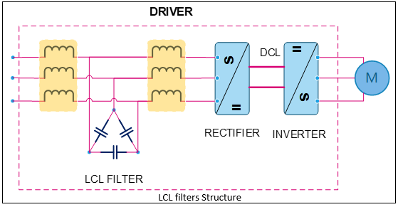
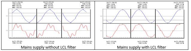
- Active filter front end with LCL filter
LCL filters are specially designed to reduce harmonics of current absorbed by power converters, with a rectifier input stage (Frequency converters for motors, UPS, etc.). Mainly, they are made of a parallel-series combination of reactors and capacitors adapted to reduce the THD(I) of rectifiers. They are specially designed to reduce the THD(I) to values of approximately 8%.
- Parallel active filter
Parallel active filter which means the current doesn’t go through the filter.Active filters use a set of transistors and capacitors to filter the current wave by injecting inverse currents to cancel out the undesired harmonic components.Parallel active filters are significantly more expensive than passive filters and take up more space.
Parallel active filters can work with multiple drives. When the filter reaches its limit, it won’t overload. In addition, if a filter breaks, it won’t stop the motor, it just won’t filter the current wave.
Parallel active filters can work with multiple drives. When the filter reaches its limit, it won’t overload. In addition, if a filter breaks, it won’t stop the motor, it just won’t filter the current wave.

H. Harmonics mitigration overview
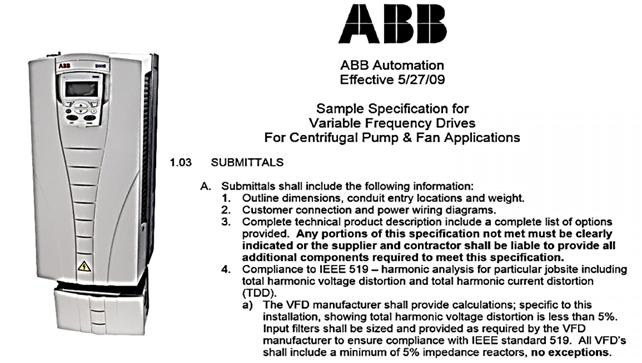
I. Manufacturer recommendation
- VFD Manufacturer recommendation
The use of an AC line reactor (which must be ordered separately) is mandatory on these drives if a special transformer is not used.
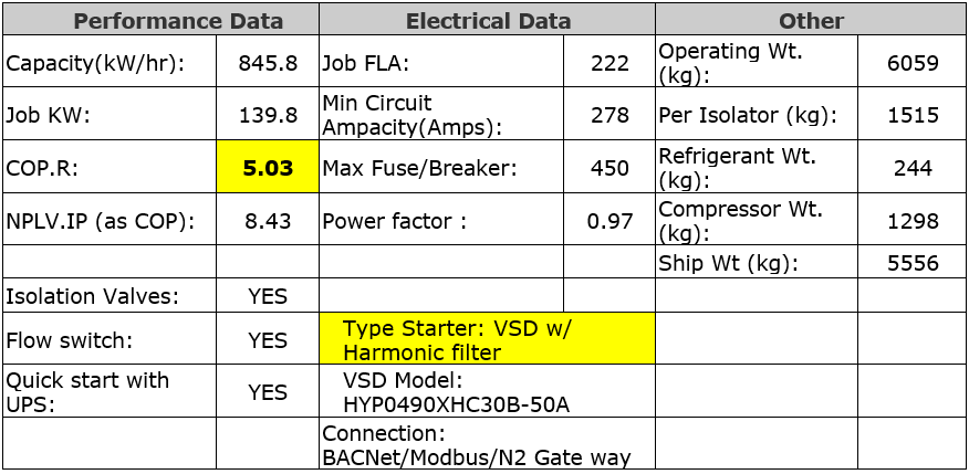
- VFD option of chiller which has harmonic filter
York’s chiller spec
- VFD option of pump which has EMC filter (GRUNDFOS hand book)
Other articles
- Sigma launched the awareness training program on ISO 9001:2015, 45001:2018 & 14001:2015 (02/03/2023)
- Sigma implements the ISO 45001:2018 management system audit and monitoring program (20/10/2022)
- Sweating on HVAC system during operation (28/09/2020)
- Why is Ventilation so Important for Buildings? (19/08/2020)
- 5S methodology was implemented at Mikazuki Spa & Hotel Resort Danang project (10/12/2019)
- Advantages of Automatic balance valve in the Chiller system (03/10/2019)
- Some notes in the desgin of the domestic hot water system (19/09/2019)
- Sigma maintaining the quality assurance work at the project (03/09/2019)
- The activities of internal quality management at the project (12/01/2017)
Partners


_thumbcr_130x97.png)


Ha Noi Head Office
 Address : 27th Floor, Block A, HUD Tower,
No.37 Le Van Luong Street, Thanh Xuan Ward, Hanoi, S.R Vietnam
 Email : sme@sigma.net.vn
 Tel : (84-24) 3 9288683 | (84-24) 3 9289235
 Fax : (84-24) 3 9288667
http://www.sigma.net.vn
Sigma Engineering JSC
Business license number 0101600518 issued by Hanoi Department of Planning and Investment on January 25, 2005
.png)
